Computational Sculpture: After Karen Bexfield, part 1
[art opencascade 3dprinting mathematica santafe sculpture Inspired by a walk down Canyon Road on an October Saturday morning, I had many inspirations for sculptural works that could have a flavor of mathematics, computation, and advanced manufacturing. At Winterowd, I came across work by Karen Bexfield, whose schtick is kiln-formed glass truncated bi-cones with holes in the surface:
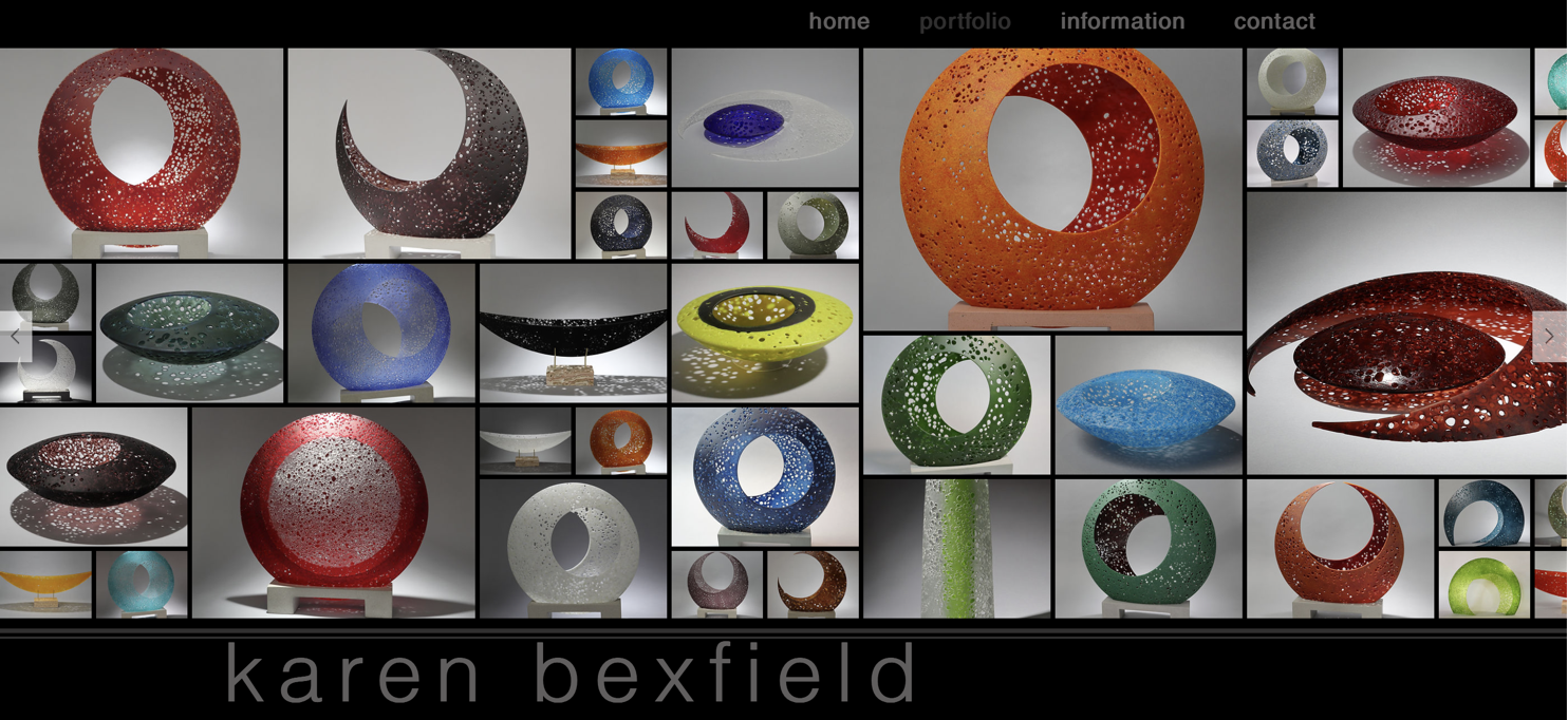 How would you generate a family of these objects computationally, within the constraint of FDM?…
A few preliminary considerations:
-
There are two families of objects in the website image above: The first consists of two sliced cones, where both faces are conic sections. The second consists of a deformed flat surface. I will start with the former. For the initial attempt I will consider the circle planes as all parallel, but we can experiment with this later.
-
Maximum x-y size on the Prusa MK3s+ is 8.3 inches–so define a maximum radius of 4 inches for the outer circle
-
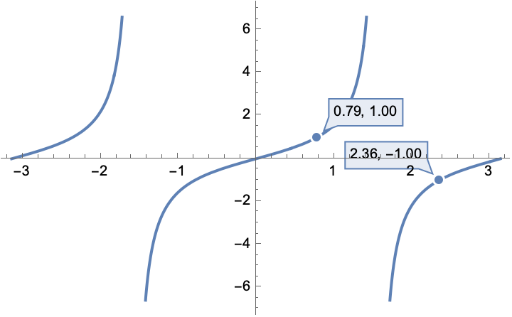
We want a self-supporting surface, so angles have to be with 45-135 degrees, or stated another way, the tangent of the angle (rise over run) has to be greater than 1 or less than -1
Plot[
  Highlighted[ Tan[x] , Placed ["Ball", { {Pi/4}, {3 Pi/4}}]],
  {x, -Pi, Pi}]
-
Height can be different for the two halves, so experiment.
-
The holes that are punched should vary in size by a small amount and be places quasirandomly (note the uniformity…) in the solid area. We can do this by generating an initial sample of point placements and then use the Lloyd algorithm to make the distances between points more uniform (while still keeping their placement random), and sampling diameters with some normal distribution.
-
We will sketch out some basic visualizations and feasibilities in an interactive way, and then generate the object using OpenCascadeLink.
Explorations in feasibility and aesthetics
We define each cone in terms of the following variables:
-
R: radius of the baseline circle (which we will set to 4)
-
h: height to the smaller circle
-
r: radius of the smaller circle
-
o: offset distance from the center
-
a: angle of rotation of the offset vector
Any given object will have two different sets of {r, o, h, a} to consider. We consider the central circle to be a {R, 0, 0, 0} as a reference origin, and only one of the circles needs to have a nonzero a. We always consider the smaller disks as contained within the central circle, r+o < R, and all variables are positive. It will also be aesthetically nicer if h<R/2. In practice we also want r to be some finite positive number, at least 0.5 inches; in practice you do not need to worry about this lower bound, because it is limited by the h and R constraints
Feasibility: What parameter choices are consistent with FDM?
We want to maintain an angle from the base to edge that is with +45 degrees of vertical for it to be self supporting for each of the truncated cones.
The rise is just the height, h, and if both circles share the same center, then the run is just R-r. If there is an offset then the run becomes at its smallest R-r-o, and at its largest it becomes R-r+o. If the base circle is centered at zero, then we just have the single relationship of (1-r) in the denominator. However if we displace it from the center by some vector of length o, then we will have one shortest and one longest distance that need to satisfy this constraint. We also will not allow our base circle to wander outside the base area (although this is not strictly necessary). The angular offset, a, does not matter because of the symmetry of the problem
allowedParameters = With[
     {R = 4},
     ImplicitRegion[
      ( (h/(R - r + o) >= 1 || h/(R - r + o) <= -1)) &&
       ( ( h/(R - r - o) >= 1 || h/(R - r - o) <= -1) ) &&
       (o + r) <= R ,
      { {r, 0.5, R}, {o, 0, R}, {h, 0, R}}]];

RegionPlot3D[allowedParameters,
  PlotTheme -> "Scientific",
  AxesLabel -> {"r", "o", "h"}]
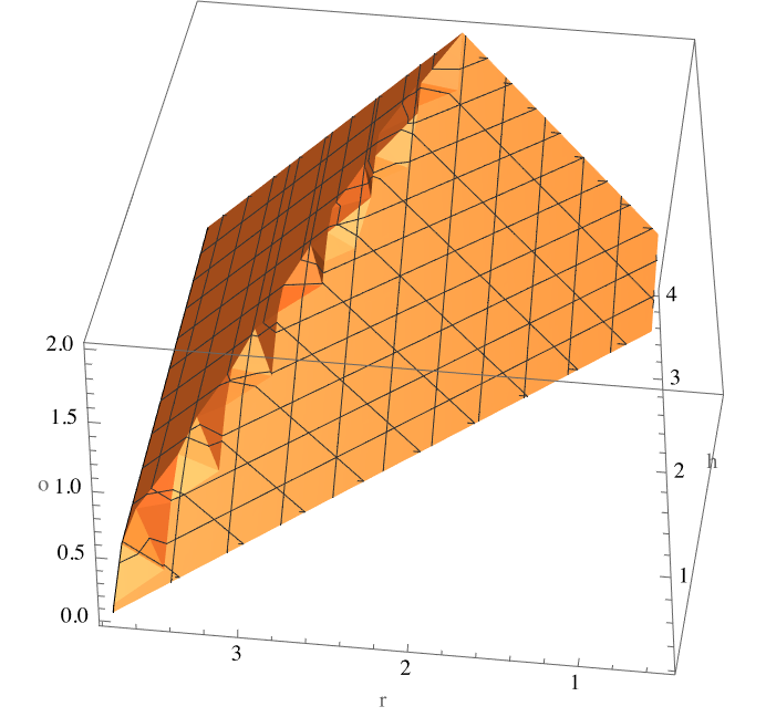
Defining a region allows us to quickly check for region membership (I suppose we could define a function too) and also generate a uniform sample of allowed parameter choices:
RegionMember[allowedParameters]@{0.5, 0.5, 2}
RandomPoint[allowedParameters]

(*False*)

(*{3.50937, 0.382735, 1.45485}*)
Aesthetics
Goal: Create a interactive graphic that shows punches and disks in the 2D plane; also shows the height profiles in the 2D plane:
ClearAll[sideProfile]
sideProfile[disk_Association ] := With[
    {offsetDirection = If[disk["a"] > 0, -1, +1]},
    With[
     {left = {-disk["r"] + offsetDirection*disk["o"], disk["h"]},
      right = {+disk["r"] + offsetDirection*disk["o"], disk["h"]}},
     {disk["color"], Line[{left, right}]}]]

topProfile[disk_Association] := With[
    {c = Circle[{0, disk["o"]}, disk["r"]]},
    {disk["color"], Rotate[c, disk["a"], {0, 0}]}]

sideView[disks_List] := Graphics[
    Map[sideProfile, disks]~Join~{White, Line[{ {0, -4}, {0, +4}}]}]

topView[disks_List] := Graphics@Map[topProfile]@disks

allowedQ[design_List] := With[
    {params = Abs@Lookup[design[[{1, -1}]], {"r", "o", "h"}]},
    AllTrue[params, RegionMember[allowedParameters]]]

allowedGraphic[design_?allowedQ] := Graphics[]
allowedGraphic[_] := Graphics@{Opacity[0.2], Black, Rectangle[{-4, -4}, {+4, +4}]}

randomDesign[] := With[
   {pts = RandomPoint[allowedParameters, 2],
    a = RandomReal[Pi/4]},
   {<|"r" -> pts[[1, 1]], "o" -> pts[[1, 2]], "h" -> -pts[[1, 3]], "a" -> 0, "color" -> Red|>,
    <|"r" -> 4, "o" -> 0, "h" -> 0, "a" -> 0, "color" -> Black|>,
    <|"r" -> pts[[-1, 1]], "o" -> pts[[-1, 2]], "h" -> pts[[-1, 3]], "a" -> a, "color" -> Blue |>}]
Use this to create a manipulative:
With[
  {init = randomDesign[]},
  Manipulate[
   With[
    {design = {
       <|"r" -> r1, "o" -> o1, "h" -> h1, "a" -> 0, "color" -> Red|>,
       <|"r" -> 4, "o" -> 0, "h" -> 0, "a" -> 0, "color" -> Black|>,
       <|"r" -> r2, "o" -> o2, "h" -> h2, "a" -> a, "color" -> Blue |>}},
    CopyToClipboard[design];
    GraphicsRow[
     {Show[sideView[design], allowedGraphic[design]],
      topView[design]}]],
   { {r1, init[[1, "r"]]}, 0.5, 4}, { {o1, init[[1, "o"]]}, 0.0, 4},
   { {h1, init[[1, "h"]]}, -4, 0.01}, { {r2, init[[-1, "r"]]}, 0.5, 4},
   { {o2, init[[-1, "o"]]}, 0.0, 4}, { {h2, init[[-1, "h"]]}, 0.01, 4},
   { {a, init[[-1, "a"]]}, 0, Pi}
  ]]
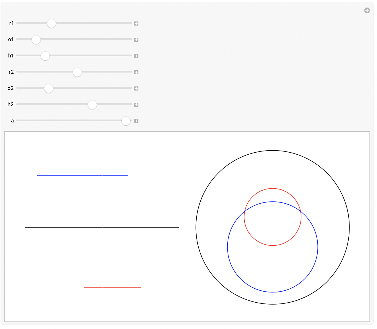
Results are always copied to the clipboard for later use…

Defining an Object in OpenCascade
For building these types of objects we definitely want to use OpenCascade (which we have used in a previous episode):
Needs["OpenCascadeLink`"]
Base object
n = {0, 0, 1};
shellThickness = 0.02; (*2 mm in inches; vase mode  will reduce to a single extrusion width, but this lets us see whats up could also have a solid object if you set the top layer count to zero; you shouldn't have to change the perimeter count, because vase mode will overide *)

s = MapThread[
    OpenCascadeShapeTransformation[
      OpenCascadeShape[OpenCascadeCircle[{ {0, #2, #3}, n}, #1]],
      RotationTransform[#4, n]] &,
    Transpose@Lookup[example, {"r", "o", "h", "a"}]];
loft = OpenCascadeShapeLoft[s, "BuildSolid" -> True];
Check the face indexing; OpenCascade will crash without warning if you try to remove the wrong faces in the shelling operation:
ColorData[3, "ColorList"][[Range[10]]]
OpenCascadeShapeSurfaceMeshToBoundaryMesh[loft]["Wireframe"["MeshElementStyle" -> FaceForm /@ ColorData[3, "ColorList"]]]

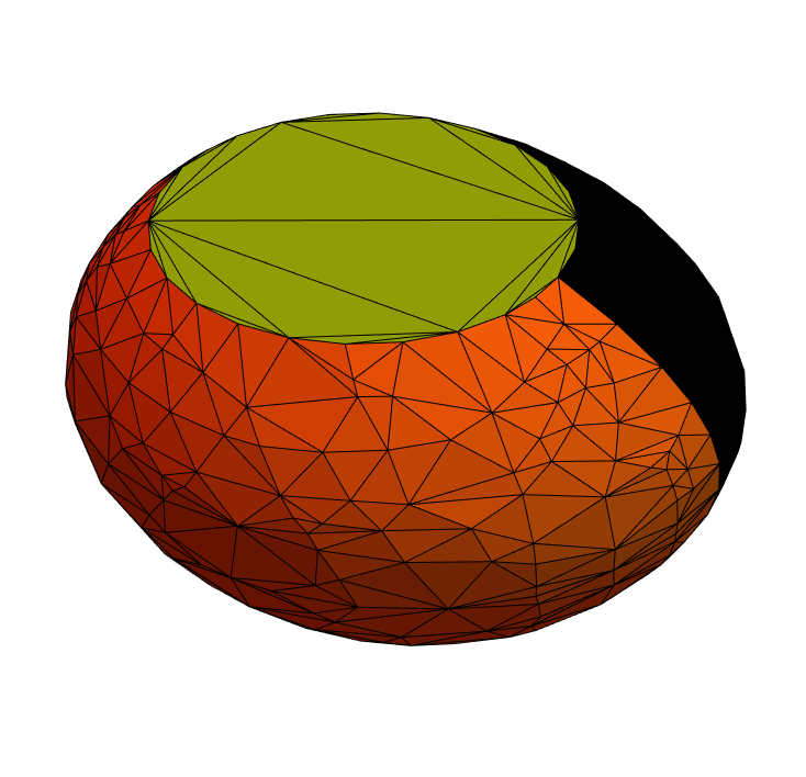
Apparently surfaces 1 and 2 are the lofted surface:
(*apparently surfaces 1 is the lofted surface...*)
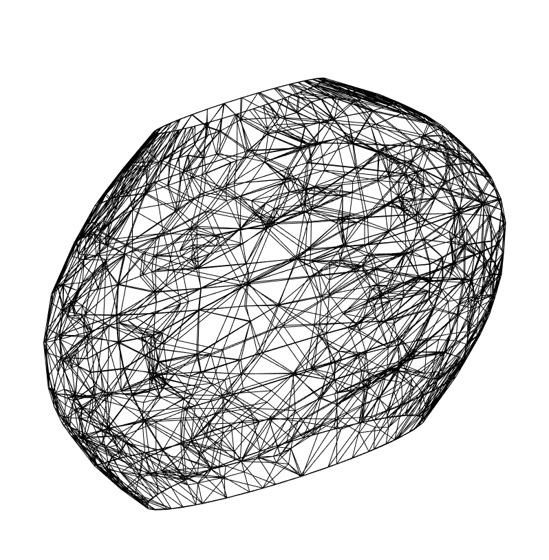
  shell = OpenCascadeShapeShelling[loft, shellThickness, {3, 4}];

   OpenCascadeShapeSurfaceMeshToBoundaryMesh[shell]["Wireframe"]
   OpenCascadeShapeExport["foo.stl", shell];
(*86 is the gematria of Elohim*)
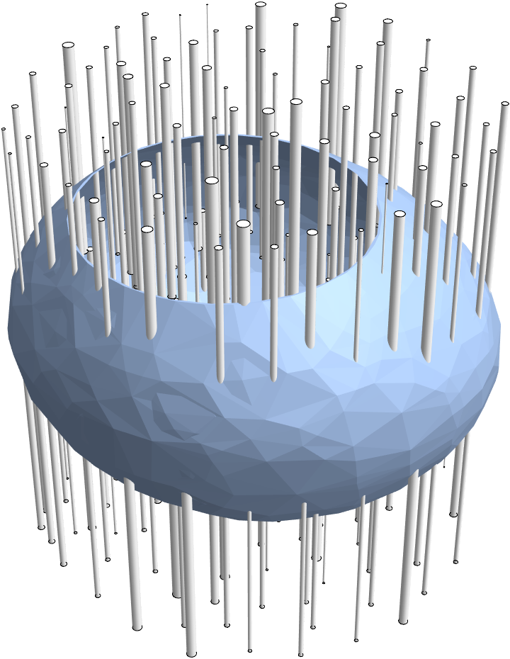
  punch[direction_ : 1, count_ : 86] := With[
     {boundary = Disk[{0, 0}, 4]},
     With[
      {centers = ResourceFunction["LloydAlgorithm"][
         RandomPoint[boundary, count], boundary, 2],
       radii = RandomVariate[NormalDistribution[0.05, 0.02], count]},
      MapThread[
       If[#2 > 0,
         Cylinder[ {Append[0]@#1, Append[4*direction]@#1}, #2],
         Nothing] &,
       {centers, radii}]]]

   punches = Flatten[{punch[1], punch[-1]}];

   Show[
    Import["foo.stl"],
    Graphics3D[punches]]
punched = Fold[
    OpenCascadeShapeDifference[#1, OpenCascadeShape[#2]] &,
    shell, punches];
OpenCascadeShapeSurfaceMeshToBoundaryMesh[punched]["Wireframe"]
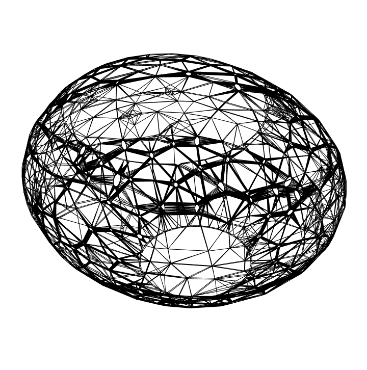
OpenCascadeShapeExport["bar.stl", punched];
Import["bar.stl"]
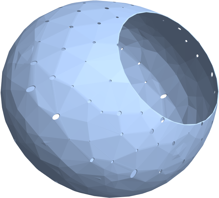
However, should you import this hollow object into PrusaSlicer, you get all manner of mesh errors and unsupported errors. It simply will not work! ** So we are going to adopt another strategy. We keep the solid object, and just let the slicer handle the shelling. **Spoiler alert: This works much better. You can just use the simple vase mode settings (it works better than trying to do fake vase mode style object definition; if you do that you will get columns for the posts all the way up which adds to the print time (and they would have to be removed):
punched2 = Fold[
    OpenCascadeShapeDifference[#1, OpenCascadeShape[#2]] &,
    loft, punches];
OpenCascadeShapeExport["bar2.stl", punched2];
Import["bar2.stl"]
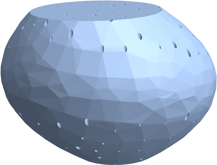
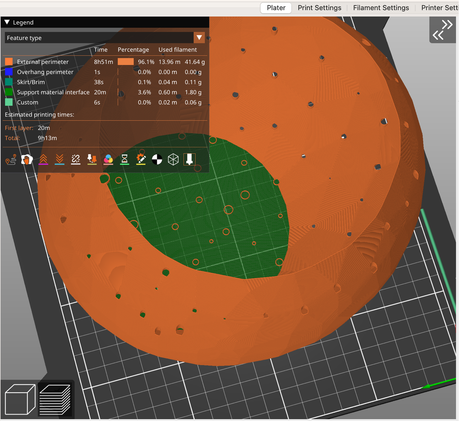
Import this into PrusaSlicer and use the default vase settings (and 0.1mm layer height and a 1 layer raft, set the top and bottom layer counts to zero) and you are good to go:
Some aesthetic comments and future directions
To make this self supporting, the rise/run behavior has to be much more shallow than what you see in the example Bexfield sculptures, so ours looks more like a lumpy potato :-)
It may be more interesting to try another strategy; the ones with the flattened base could be self supporting in that axes. But we will leave that for a future project…
Notes on 3D-printing
Reduction to practice awaits getting back home to my printer. In the meantime, some notes on materials and settings:
- Vase mode slicing: probably just use the default Prusa 0.45 mm extrusion width (for the default 0.4mm nozzle), and a 0.1mm layer height for maximum smoothness.
- Turn on a raft (maybe just one layer) and orient it so the largest circumference side is on the bottom for maximal adhesion support
- Vase mode slicing in PrusaSlicer does not like the hole punched files; weird mesh output which results in disconnected regions. Design solids instead, as demonstrated above.
- This post suggests that if you design a 0.5mm thickness wall (=0.02 inches) that holes are OK in vase mode, but you cannot have two holes in the same vase perimeter.
- Another fun trick: you can print reinforced solid objects by inserting 0.4mm cut ribs into your model; using vase model in this way dramatically reduces the print time. Here is an example for printing RC models where this acts as stiffening (with some more how-to tips in Fusion360 than the earlier video)
- People do really cool stuff with Vase mode. Get some inspiration.
-
Matterhackers sells a variety of translucent PLA and PETG filaments. From what I gather, the translucency of PETG appears a bit nicer, so this might present an opportunity to experiment with a new material.
- Glass 3d-printing exists.
- Maple Glass (Australia) essentially does FDM with glass rods in a kiln. (They also sell a gadget to melt glass and make filaments).
- Glassomer sells a glass-based SLS resin (formulated for 365nm, 385nm and 405nm–the latter being the wavelength of the Prusa SL1S), but alas, the build area is only 5 x 3.14 inches, so too small for works like these.
- (01 Aug 2024) Virtual Foundry sells a standard FDM-printer compatible borosilicate filament—print it on your ordinary printer and then debind and sinter it in a kiln to make a true glass object (some dimensions may change…) Sintered parts will not be optically clear.
ToJekyll["Computational Sculpture: After Karen Bexfield, part 1", "art opencascade 3dprinting mathematica santafe sculpture"]