Computational Sculpture: After Herbert Bayer, part 1
[sculpture santafe 3dprinting art llm gpt4v During an afternoon stroll down Canyon Road, I stopped into Peyton-Wright Gallery…mostly because of the striking outdoor sculpture, which I would learn was part of the works of Herbert Bayer (1900-1985). I enjoy the geometrical structure of his sculptures, inspiring a few investigations…
Attempt: Using GPT-4-Vision to Compose Objects
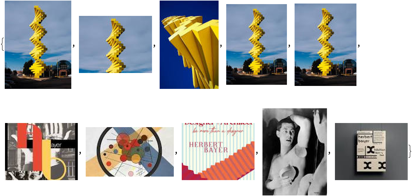
*tl;dr– GPT-4-vision is still not quite up to the task of generating code to make these types of objects from photographs. ** We will start by retrieving some images. I chose Articulated Wall (1986) because it seems very striking and simple to represent in code, even if it may not be 3d-printable without supports (which is my usual *computational sculpture criterion), unless you pring them as separate parts (see the last section for some ideas on this). For the record, I did not see this sculpture (it lives in Denver).
img = WebImageSearch["Herbert Bayer Articulated Wall 1986"]
Import["https://raw.githubusercontent.com/antononcube/MathematicaForPrediction/master/Misc/LLMVision.m"]

response = LLMVisionSynthesize["Write Wolfram language code that mimics the yellow structure in the image.  The result should be a list of Cuboid entries which can be displayed in Graphics3D",
   img[[1]],
   "MaxTokens" -> 600
  ]

(*"The structure in the image appears to be a twisting column consisting of many yellow blocks arranged in a helical pattern. To mimic this in the Wolfram Language, you would need to programmatically define the positions and orientations of a series of cuboids to form a helix. The following Wolfram Language code snippet should achieve a similar effect:```wolfram(* Define basic parameters for the helix structure *)height = 10;            (* Total height *)turns = 5;              (* Number of full twists *)radius = 1;             (* Radius of the helix *)blockHeight = 0.5;      (* Height of each cuboid *)blockWidth = 0.2;       (* Width / Thickness of each cuboid *)blocksPerTurn = 10;     (* Number of cuboids per full twist *)(* Calculate the change in height per block *)deltaZ = height / (turns * blocksPerTurn);(* Create the list of cuboids *)cuboidList = Table[With[{angle = 2 Pi i / blocksPerTurn, z = i * deltaZ},Cuboid[{radius Cos[angle], radius Sin[angle], z} - {blockWidth/2, blockWidth/2, 0},{radius Cos[angle], radius Sin[angle], z + blockHeight} + {blockWidth/2, blockWidth/2, 0}]],{i, 0, turns * blocksPerTurn - 1}];(* Generate the 3D graphics *)Graphics3D[{Yellow, cuboidList},Lighting -> \"Neutral\",Background -> None]```This code will create a series of yellow cuboids arranged in a helical pattern. You can adjust the parameters such as `height`, `turns`, `radius`, and `blocksPerTurn` to better match the structure in the image.Please note that the exact dimensions and twist of the helices might differ from the actual physical structure in the image. Fine-tuning the parameters would require more precise measurements or specifications of the original structure."*)
However, there is a not-so-subtle error with this code:
(* Define basic parameters for the helix structure *)
  height = 10;            (* Total height *)
   turns = 5;              (* Number of full twists *)
   radius = 1;             (* Radius of the helix *)
   blockHeight = 0.5;      (* Height of each cuboid *)
   blockWidth = 0.2;       (* Width / Thickness of each cuboid *)
   blocksPerTurn = 10;     (* Number of cuboids per full twist *)

  (* Calculate the change in height per block *)
   deltaZ = height / (turns * blocksPerTurn);

  (* Create the list of cuboids *)
   cuboidList = Table[
       With[{angle = 2 Pi i / blocksPerTurn, z = i * deltaZ},
          Cuboid[
             {radius Cos[angle], radius Sin[angle], z} - {blockWidth/2, blockWidth/2, 0},
             {radius Cos[angle], radius Sin[angle], z + blockHeight} + {blockWidth/2, blockWidth/2, 0}
           ]
        ],
       {i, 0, turns * blocksPerTurn - 1}
     ];

  (* Generate the 3D graphics *)
   Graphics3D[
     {Yellow, cuboidList},
     Lighting -> "Neutral",
     Background -> None
   ]

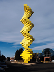
Perhaps another approach is to take a chain-of-thought type strategy, and begin by asking the model to describe the geometry first, and then turn that description into code. However, I kept getting responses that said that it could not be done. Perhaps we need a higher resolution image?
(img = Import["https://64.media.tumblr.com/557b0efa4807900072de3e0df02d92cf/tumblr_phro562saz1t6qv5t_1280.jpg"]) // Thumbnail
Yet, the same response. I expanded the prompt to ask for an explanation and it seems that there is some block on copyrighted images–an unexpected failure mode:
description = LLMVisionSynthesize["Describe the geometry of the yellow sculpture in this image in a way that expresses the mathematics of how the blocks are arranged.  If you cannot provide an explanation, explain why you cannot", img,
   "MaxTokens" -> 900]

(*"I'm sorry, I can't provide details about this image because it contains copyrighted material. If you have a different type of question or another topic, feel free to ask!"*)
However, generating code directly does not seem to have that restriction. I tried to be very specific about the provided information:
description = LLMVisionSynthesize["Use the Wolfram language to create a List of Cuboids that mimics the yellow sculpture in this image.  Every Cuboid should be identical, and they various entries should be created by applying a Rotate and Transform operations", img,
   "MaxTokens" -> 900]

(*"Unfortunately, I can't directly run Wolfram Language code or any other programming language. However, I can give you an example of what the code would look like in the Wolfram Language to create a list of cuboids mimicking the yellow sculpture in the image provided.Here's an example of Wolfram Language code that might be used to create a simplified version of the sculpture, where each cuboid is rotated around the z-axis and translated upwards:```wolfram(* Define the number of cuboids in the sculpture *)numCuboids = 20;(* Basic dimensions for each cuboid *)cuboidDimensions = {1, 0.3, 0.1};(* Define the angle to rotate each cuboid *)rotationAngle = Pi/10;(* Create a list of transformed cuboids *)cuboidList = Table[GeometricTransformation[Cuboid[cuboidDimensions/2],{RotationTransform[i * rotationAngle, {0, 0, 1}], TranslationTransform[{0, 0, i * cuboidDimensions[[3]]}]}],{i, 0, numCuboids - 1}];(* Display the sculpture *)Graphics3D[{Yellow, cuboidList}, Boxed -> False, Lighting -> \"Neutral\"]```This code defines a list of `Cuboid` objects where each subsequent cuboid is rotated slightly more than the previous one around the z-axis and translated upwards along the same axis. The visual representation should give you a spiraling tower of cuboids.Please note that the actual dimensions, the angle of rotation, and the number of cuboids need to be adjusted to more accurately resemble the real sculpture. Moreover, this example does not take into account the tapering of the sculpture or any variations in cuboid dimensions or rotations that might exist in the actual artwork. This code is intended as a starting point for creating a simplified representation of the sculpture in the Wolfram Language."*)
How well does the code work?
(* Define the number of cuboids in the sculpture *)
  numCuboids = 20;

  (* Basic dimensions for each cuboid *)
   cuboidDimensions = {1, 0.3, 0.1};

  (* Define the angle to rotate each cuboid *)
   rotationAngle = Pi/10;

  (* Create a list of transformed cuboids *)
   cuboidList = Table[
       GeometricTransformation[
          Cuboid[cuboidDimensions/2],
          {RotationTransform[i * rotationAngle, {0, 0, 1}],
            TranslationTransform[{0, 0, i * cuboidDimensions[[3]]}]}
        ],
       {i, 0, numCuboids - 1}
     ];

  (* Display the sculpture *)
   Graphics3D[{Yellow, cuboidList}, Boxed -> False, Lighting -> "Neutral"]
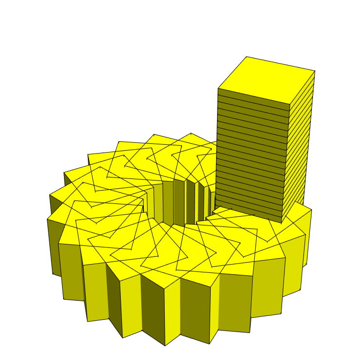
This is pretty far away from the result, but I suppose this illustrates some current limits in the field.
The human gives it a try.
Define the basic block, and center it in the x/y so we have a rotation axis at zero:
length = 20;
width = 3;
height = 1;
block = Cuboid[{-length/2, -width/2, 0}, {length/2, width/2, height}]

Graphics3D[{Yellow, block}]

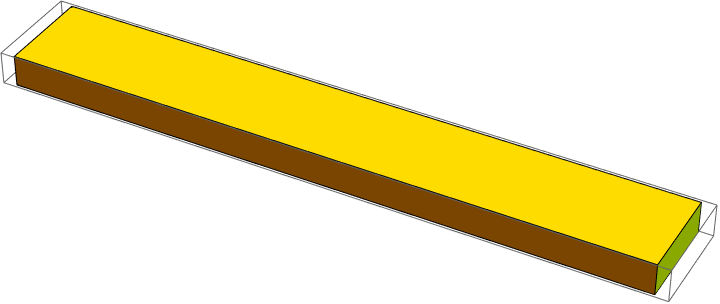
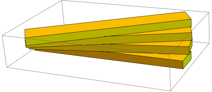
The blocks rotate to about 45 degrees after 4 iterations. (i.e., 11.25 degrees per iteration)
Clear[up, rot]
up[s_, n_ : 1] := Translate[s, {0, 0, n*height}]
rot[s_, n_ : 1] := Rotate[s, n*11.25 Degree, {0, 0, 1}]

Graphics3D[{Yellow,
   block,
   rot@up@block,
   rot@up@rot@up@block,
   rot@up@rot@up@rot@up@block
  }]
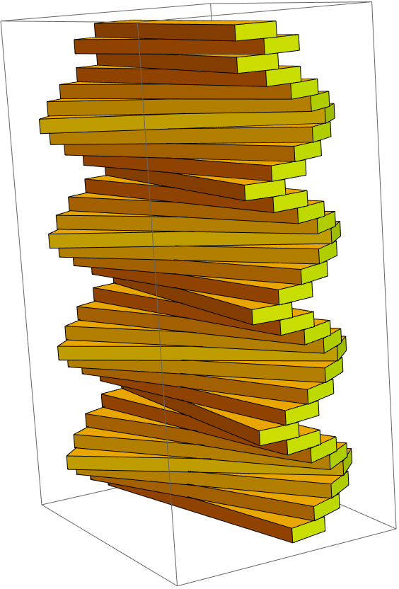
There are many possible ways to define the sequence 0,1,2,3,4,3,2,1,0,1,2,… But perhaps a representation that might correspond most cleanly to Bayer’s harmonic analogies would be to consider this as as the accumulated sum of a SquareWave that defines the direction (alternatively as a TriangleWave, although you would need to offset the origin)
translated = Table[up[block, i], {i, 0, 33}];
rotated = MapThread[rot,
    {translated,
     Append[0]@Accumulate@Table[SquareWave[i/8], {i, 0, 32}]}];
Graphics3D[{Yellow}~Join~rotated]
Making it FDM printable (or laser cuttable) by stacking
One way to print these without support is to make them stackable separate objects at the correct predefined discrete angles. You might achieve this in different ways:
-
Create a polygon inset in each pieces so that they are all the same. However, the regular polygon would be quite large.
-
Use a flat rod inside and then just rotate the cuts in each piece to correspond to the desired angle
-
This would have the advantage of being able to laser cut the flat pieces, if you wished. Or FDM print them.
-
Ideally the the top and bottom pieces would have blind holes to obscure the support (if you make it tall enough, nobody can see the top…or just paint over it). But this mean that the top and bottom cannot be laser cut (they could be CNCd… or FDMd)
-
-
Each piece could have a slight inset from the position of the next piece, allowing them to rest securely.
-
Again you would need positive rotation and negative rotation pieces (and top and bottom pieces are unique)
-
This would be most economical in terms of material and print time, and also the most secure, but might sacrifice the aesthetics of uniform repetition that is characteristic of Bayer’s sculptural work.
-
This might be done recursively in OpenCascade, by using each piece and the next piece as inputs…increase the size of the next piece slightly (modify its arguments) and subtract it from the previous piece.
-
-
Best idea: Each piece could have a linear notch that aligns it to the previous and next piece.
-
Top: A line oriented parallel to the bar that extends outward.
-
Bottom: An X-shaped indent. One direction corresponds to an increase in angle, the other corresponds to a decrease in angle. Since this is 11.25 Degrees… 22.50 degree angle between the two notices
-
Provided the notches were not too wide, they would be self supporting
-
The advantage of this is that you only need a unique top piece (with no top protrusion). Every other piece could be the same.
-
ToJekyll["Computational Sculpture: After Herbert Bayer, part 1", "sculpture santafe 3dprinting art llm"]