Building a MIDI to CV converter with the RP2040 (part 2)
[music electronics pico analog synth i2c python In a previous post, we defined some of the ideas and resources for the system. Along the way, we’ll learn a bit about I2C programming on the Pico and MCP4728 DAC. In this post, we’ll actually build the MIDI to CV gadget…
Bill of materials
- Adafruit MIDI featherwing includes optoisolator and jacks. $6.95
- Adafruit MCP4728 Quad DAC $7.50 DATASHEET
- Breadboard-friend 3.5mm audio jacks $0.95/each. Buy a couple
- (optional) 74AHCT125 3.3/5V level shifter ($1.50)
- Raspberry Pi Pico (save yourself some effort and get the Pico H which comes with headers already soldered on) – Pinout diagram
- Breadboard
Load a Micro Python boot image
Load your favorite Micro python environment bootimage. Here we use rp2-pico-20220618-v1.19.1.uf2
Scanning for I2C devices and their addresses
Further reading and tutorials hackster.io & MicroPython for Kids
The Pico has two I2C hardware controllers. Each controller can talk to multiple I2C devices as long as all the devices communicating on each controller have distinct addresses.
I2C0 SDA are on GPIOs 0, 4, 8, 12, 16 and 20 I2C0 SCL are on GPIOs 1, 5, 9, 13, 17 and 21 I2C1 SDA are on GPIOs 2, 6, 10, 14, 18 and 26 I2C1 SCL are on GPIOs 3, 7, 11, 15, 19 and 27
If using a plain old Pico, you can select any SDA/SCL pair on the same I2C controller. But it is convenient to use pins GP16 & GP17 (which are on I2C0), as these are the Pins that correspond to a QWIIC connector on devices like the Sparkfun MicroPro and their adafruit equivalents.
Hook up the MCP4728 breakout board Vcc and GND pins to the Gnd and 3V3(OUT) pins on the Pico. Connect the SCL and SDA pins on the MCP4728 breakout to the SCL (GP17) and SDA (GP16) pins on the pico. When you apply power the the pico, a green LED on the breakout board should light up. Let’s see what addresses report back:
import machine

I2C_SDA_PIN = 16
I2C_SCL_PIN = 17
i2c=machine.I2C(0,sda=machine.Pin(I2C_SDA_PIN), scl=machine.Pin(I2C_SCL_PIN), freq=400000)

print('Scanning I2C bus.')
devices = i2c.scan() # this returns a list of devices

device_count = len(devices)

if device_count == 0:
    print('No i2c device found.')
else:
    print(device_count, 'devices found.')

for device in devices:
    print('Decimal address:', device, ", Hex address: ", hex(device))
Our little MCP4728 dutifully reports back at Decimal address: 100 , Hex address: 0x64
Sending a CV voltage sweep
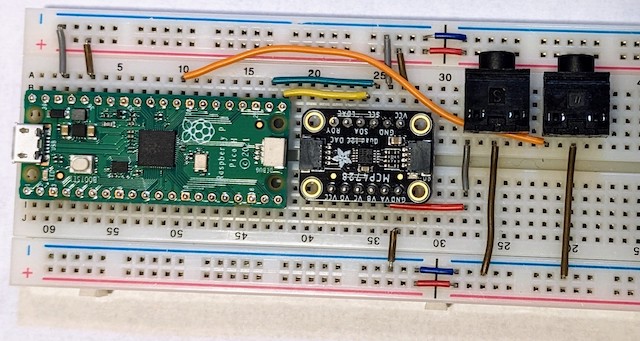
Wire up VA on the MCP4728 breakout board to the output pin on the audio jack and wire the other output jack pin to ground. Here’s a photo of the layout:

There’s a MicroPython port of the MCP4728 library online Grab a copy and save it on your Pico as mcp4728.py. The README describes the functionality, most of which we won’t use (yet).
Now run the following:
from machine import Pin, I2C
from time import sleep
import mcp4728 # https://github.com/openfablab/mcp4728

I2C_SDA_PIN = 16
I2C_SCL_PIN = 17
MCP4728_I2C_ADDRESS = 0x64

#initialize I2C
i2c=I2C(0, sda=Pin(I2C_SDA_PIN), scl=Pin(I2C_SCL_PIN), freq=400000)

# sanity checK: are there devices on the I2C bus
devices = i2c.scan()
print("i2c devices found: ", [hex(i) for i in devices])

# initialize DAC
dac1=mcp4728.MCP4728(i2c, MCP4728_I2C_ADDRESS)

# sweep values
while (True):
    for i in range(4096):
        dac1.a.value = i
        sleep(0.001)
Hook up the output jack to the CV-in on your VCO and you’ll here a nice voltage sweep.
Troubleshooting note and commentss:
- OSError 5 corresponds to the I2C device not responding. Most of the advice you’l find online is about wrong address specifications, etc. So as a sanity check, I check for the device in the code above. However, this is not the only problem that can arise: a slightly loose connection to SDA/SCL can allow for finding the devices but still causing this error when actually reading or writing to the device. So try reseating your breadboard connections if you encounter this error.
- AxWax’s circuit diagram shows the MCP4728 VCC connected to the Pico’s VBUS (which will be at 5V). I believe this to be mistaken. While the MCP4728 can operate at either 3.3V or 5V, it’s going to take 3.3V logic levels from the pico. So it is more appropriate to wire it the way I describe.
Gate trigger
Next up, we’ll configure a GPIO logic pin to sent a gate trigger. Wired this up from GP22 to a wiring pin. Here’s a photo:

BUT the mki x es.EDU envelope generator is only triggered by 4.1 V or above! So our lowly little 3.3V logic output won’t be enough to trigger it.
Two options:
- Replace R9 on the EG with a 22 k Ohm resistor (instead of 47 k Ohm in the nominal plan) so that a 2.4 V threshold is enough to trigger it.
- Use a level shifter like the 74AHCT125 to convert the output from 3.3 to 5V. We want to convert a 3.3V signal to a 5V signal, so we would apply 5V power to the VCC pin, common ground to the ground pin, and tie the /OE (output enable) pins to ground. Data goes in (from the Pico) on the A pins and goes out on the matching Y pins.
After thinking about it a bit, I elected to modify the EG, as it seemed like it would help future projects and keep this one simpler. But I tested the output with a volt meter. Here’s the code:
from machine import Pin, I2C
from time import sleep
import mcp4728 # https://github.com/openfablab/mcp4728

I2C_SDA_PIN = 16
I2C_SCL_PIN = 17
GATE_PIN = 22
MCP4728_I2C_ADDRESS = 0x64

#initialize connections to I2C and gate outputs
i2c=I2C(0, sda=Pin(I2C_SDA_PIN), scl=Pin(I2C_SCL_PIN), freq=400000)
gate = Pin(GATE_PIN, Pin.OUT, value = 0)

# sanity checK: are there devices on the I2C bus
devices = i2c.scan()
print("i2c devices found: ", [hex(i) for i in devices])

# initialize DAC
dac1=mcp4728.MCP4728(i2c, MCP4728_I2C_ADDRESS)

# sweep
gateState = 0;
while (True):
    for i in range(4096):
        dac1.a.value = i

        if (i%1024 == 0): # toggle the gate periodically
            gateState = (gateState + 1) % 2
            gate.value(gateState)

        sleep(0.001)
MIDI input
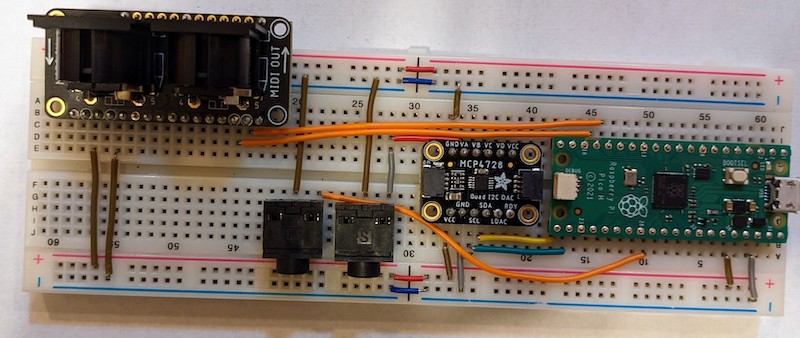
A nice aspect of using the featherwing breakout is that it comes with the optoisolator, etc. already bake in. From left to right, the circled pins are VCC = 3.3V), GND, UART RX, and UART TX. We’ll write these up to the 3.3V and ground bus lines, and then connect the UART pins to GP13 and GP12 on the Pico, respectively. There’s no good reason for this (we could have picked any other UART pair), but the wires I had were just long enough to reach these, but too long to reach the others on that side.

If you wire the power up correctly, you’ll have a blue LED shiting from the bottom of the MIDI breakout board. You’ll have to see if the code works to check that you wired the UART’s correctly.
We’ll use the SimpleMIDIDecoder.py and adapt AxWax’s code. Here’s my reworked code. Be sure to save this as main.py so that it will run whenever the Pico boots up:
from machine import Pin, I2C, UART
import mcp4728 # https://github.com/openfablab/mcp4728
from SimpleMIDIDecoder import SimpleMIDIDecoder #https://github.com/diyelectromusic/sdemp/blob/main/src/SDEMP/Micropython/SimpleMIDIDecoder.py

# Define hardware pins
I2C_SDA_PIN = 16
I2C_SCL_PIN = 17
GATE_PIN = 22
MCP4728_I2C_ADDRESS = 0x64
UART_RX_PIN = 13
UART_TX_PIN = 12

# Define note mapping constants
lowest_note = 40       # which MIDI note corresponds to CV = 0
mv = 4096 / 5.1 / 1000 # calculate 1mV: steps / max V / 1000
semitone = 83.33 * mv  # calculate mV per semitone

# MIDI callback routines

def doMidiNoteOn(ch, cmd, note, vel):
    print("received note", note)
    voltage_setting =int((note - lowest_note)*semitone)
    if (voltage_setting > 4095 or voltage_setting <0):
        print("voltage", voltage_setting, "out of range. resetting to limits")
        voltage_setting = max( min(voltage_setting, 4095), 0)
    dac1.a.value = voltage_setting
    gate.value(1)
    print("turning on gate with DAC = ", voltage_setting)

def doMidiNoteOff(ch, cmd, note, vel):
    print("key off")
    gate.value(0)

#initialize connections to I2C, gate outputs, and uart
i2c=I2C(0, sda=Pin(I2C_SDA_PIN), scl=Pin(I2C_SCL_PIN), freq=400000)
gate = Pin(GATE_PIN, Pin.OUT, value = 0)
uart = UART(0, 31250, rx=Pin(UART_RX_PIN), tx=Pin(UART_TX_PIN))

# sanity checK: are there devices on the I2C bus
devices = i2c.scan()
print("i2c devices found: ", [hex(i) for i in devices])

# initialize DAC
dac1=mcp4728.MCP4728(i2c, MCP4728_I2C_ADDRESS)
dac1.a.value = 0

# handle notes
md = SimpleMIDIDecoder()
md.cbNoteOn (doMidiNoteOn)
md.cbNoteOff (doMidiNoteOff)

# the loop
while True:
    # Check for MIDI messages
    if (uart.any()):
        md.read(uart.read(1)[0])
And that’s when I realized….I don’t have a MIDI cable! So I have to pick one up before confirming that this works. B&H to the rescue
Update: 06 Feb 2023 And it works! I’ve added some commands to echo the received key and the voltage values to serial, as well as making sure they don’t go outside the bounds that are allowed. I haven’t quite figured out the proper way of calibration. Notes are be kind of all over, rather than being exactly in tune. But that’s part of the charm. Also swapped out the voltage divider resistors in the EG modules so that they can be triggered by the logic gates on the Pico, and that works fine now.
Next Steps/ Ideas for Future projects
Modify the EG to test the triggerGet a MIDI cable (to test MIDI)- Dig into the MCP4728 settings (voltage ranges, etc.)
- Other programmatic stuff with the ports ( 3 more CVs, clock signals, …))
- Generating a note tuning/calibration table (by frequency counting on a PWM pin)
- As the mki x es.EDU only has a single VCO, it is annoying to tie it up. So maybe just use the Pico itself as an oscillator (based on the MIDI signal) and have it generate wave outputs. Super easy to do this with a square wave and not so tough to generate an arbitrary waveform (cute idea to use a home-brew R2R DAC….I suppose we could even use that for the CV as well). Can handle frequencies higher than any human can hear. A side modification would be to put in a 10pin Eurorack header, and pull off +/-12VDC lines to power an op-amp into which you could feed the (capcitor decoupled…centered to zero) 3.3V signal so as to amplify it to the standard nominal +/-10VDC signal. While you are at it, put in a voltage regulator to power the Pico off the 12VDC eurorack supply.